This page lists the available equipment and lecture demonstrations for the MSU Department of Physics & Astronomy. Important things to note:
In addition to the equipment listed, there are video projectors, overhead projectors, slide projectors, 16mm movie projectors, several notebook computers, two large TV sets, a laser disc player, a DVD player, two VCRs, and a Flex Cam (for extreme close-ups of small items). However, each of the large lecture rooms (H150, H250, and H350) has a ceiling-mounted video projector, a PA system, a very large ring stand, and a very strong ring in the ceiling. Audio-visual equipment and some large pieces of demonstration apparatus are in H240.
Send questions or suggestions to Chase Boone.
(Click on a subject link to move to a more detailed list. In each list click on individual demo links for more details.)
| Description | Picture |
|---|---|
GENERAL USE ITEMS |
|
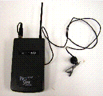
Room Specific Wireless Microphones (22C)The microphones can easily transmit to a room's PA system from other parts of the building. Therefore, make sure you have the one for your classroom or you may broadcast to someone else's class; this has happened. Also be careful that it is not on if you wear a microphone outside the classroom, for example, in the rest room. |
|
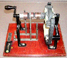
Belt-driven, variable-speed rotatorsShown at right is a rotator (12E, H240) and several accessories (14D-dr6). The rotator shaft can be adjusted so that it is horizontal, vertical, or in between. The speed of rotation is adjustable by means of a leather disk that moves against a drive plate. If the disk slips, try cleaning its rim or using belt dressing on it. CAUTION: There is no belt guard. Keep your fingers and tie away from the belt. |

|
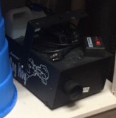
Fog Hog (H240)This device generates a fog that is useful for showing up laser beams and for filling the smoke ring cannon. Unfortunately, the fog sets off the supersensitive smoke detectors in our building resulting in a clearing of the building and a visit from the cops and fire department. Therefore, the fog machine is useful only for demonstrations done in other buildings. |
|
Flex Cam Video Camera (H240)This camera is easy to connect to the video projector either by means of usual RCA video connectors or by means of the S-Video connector. The "goose neck" allows the camera to be positioned near objects of interest and the focusing ring on the lens allows anything from extreme closeups to distant views. |

|
Vacuum Pump on Cart (cart)The vacuum pump has attached to it a large vacuum hose that has a valve for use in repressurizing evacuated vessels. There are fittings (20D-dr 1-3) that allow smaller tubing to be attached to the large hose. A mechanical gauge gives the approximate pressure. The large plexiglass screen is meant to protect the class in case there is an implosion of a bell jar. CAUTION: Protect the pump by never leaving it under vacuum when it is off and by not leaving it on when it is not connected to a closed vacuum chamber. |

|
ASTRONOMY |
|
Scale Model of Solar System (Second Floor Hallway)The scale of the model is based on the sun being represented by the yellow light bulb in the ceiling outside H250. Planet orbits are represented by colored pvc pipe in the hallway ceiling. Posters explain the scale and give additional information. Jupiter's orbit is at the far end of the hall. There is a poster showing where, on campus, the orbits of the more distant planets would be. |
|
Sun, Moon, Earth Model (1) |

|
Antique Seasons Model (2) |

|
Many (Tennis Ball) Moons (2)The tennis balls can be passed out the students to help them figure out what the moon will look like for a given position with respect to the Earth and Sun. Each tennis ball is painted black on one side, to represent the unlighted side of the moon, and unpainted on the other side, to represent the part of the moon lighted by the sun. |

|
Conic Section Model (1)This model comes apart with each piece a different color. |

|
Sunspot Viewing with Telescope(H330A)Set up one of the telescopes, with a solar filter, outdoors on the paved area in front of Hilbun Hall. Run a long extension cord through the window of H125 for the clock drive. Take students outside to the telescope or arrange to have them stop by on their way to class. |
|
Solar Eclipse ViewingNote: Both of these methods require frequent adjustments to compensate for the Earth's rotation. Besides some of the methods publicized in the media and besides using a telescope and solar filter (H330A) as with sunspots, there are several ways that have proven effective in making solar eclipse viewing available to a large group. We have an eclipse viewing stand (2) that can be used with one side of a pair of binoculars to form a real image of the sun on a white paper screen. The method that gives the largest sun image uses a very small plane mirror (18E-dr9) on a stand about 30 m away to form an image of the sun on a screen inside the Hilbun breezeway. This involves the mirror equivalent of the pinhole camera. A mirror that works well is one designed to be used as part of an optical lever. |


|
MECHANICS |
|
Inertia-First Law |
|
Embroidery Hoop Drops Pen into Bottle(4F)Balance the embroidery hoop on top of the glass pop bottle and then stand a (flat-ended) ballpoint pen (or a nail head down) on the top of the hoop directly above the mouth of the bottle. Grabbing the hoop from the inside, snap it quickly from under the pen. The pen should fall into the bottle. Motion of the hand must be rapid and horizontal and must begin before contact with the hoop. Hand must grab hoop from the inside. For the case shown in the diagram the hoop will be snatched away to the right. |

|
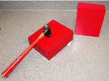
Showing Inertia of Heavy Metal Block (4D)Pounding the block: place hand palm down on table top; bridge hand a little so that insides of knuckles are not against table. With the block standing on edge on the table near the thumb side of your hand, tilt the heavy metal block over on top of back of hand. Tell students that the block's inertia will protect you when you pound the block with a hammer. Pound on the block and let them see that your hand is not injured. To ham it up a bit, for your first blow slow the hammer and just barely hit the block to let them think you are not confident. After they groan a bit, really whack the block several times. Shaking the block: indicate to the students that we sense inertia by how hard it is to accelerate objects, not by how hard it is to lift them. Show them how hard it is for you to shake the block in front of you. Explain that this would also be true under weightless conditions even though it would then be very easy to lift the block slowly. The photo below shows the steel block(with the hammer) and a styrofoam block of the same dimensions and color. |
|
Toss Styrofoam Block That Students Think Has Great Inertia(4D)Have styrofoam block the same size as and painted the same as the massive metal block. While going though the discussion of how the massive metal block would be just as hard to shake under weightless conditions, slyly switch to the styrofoam block and pretend that it is hard to lift and hard to shake. While discussing that this would mean that the block would be very hard to stop if it were moving fast, pretend to trip and send the block into the audience. CAUTION: It is possible that students who are fooled can be injured in their attempt to escape the approaching block. |
|
Handle SettingExplain how an experienced woodcutter or carpenter tightens the handle of his tool by pounding on the end of the handle rather than by pounding on the head, thus utilizing the inertia of the head Demonstrate this by tightening the loose handle of a hammer (4D). Alternatively, as illustrated at right, use the "inertia block" (5F) that consists of a massive block of wood with an aluminum rod passing through it. Pound on the end of the rod and show how the block "climbs" the rod. |

|
Card Flick-Ball Bearing Drop (4D)This demo uses a piece of commercial apparatus consisting of a base and a pedestal with a small well at the top. Place a playing card or an index card on the pedestal and place a steel ball on the card above the pedestal. Press down slightly to make a small depression that will keep the ball from rolling off. Thump the edge of the card to send it rapidly out from under the ball. The ball will fall into the well. One version of this device has, beside the pedestal, a piece of spring steel that does the "thumping." |

|
Break String below Hanging Block (4D)>Use a fairly massive block of wood that has hooks at opposite ends. Hang the block by a fairly weak string, e.g. kite string. Connect a piece of the same string to the bottom of the block. Tell the students you will pull down on the bottom string; ask which string will break first and why. They will usually use he weight of the block in arguing that the top string will break. Instead of pulling slowly as they expect, snatch down on the bottom string and use the inertia of the block in explaining why that lower string is the one to break. |

|
Pulling Dollar Bill from between Coke Bottles (4C)Balance one old-style glass pop bottle on another with their openings together. Raise the upper bottle and insert one end of a dollar bill between lips of the two bottles. Lower the bottle and balance it again. Bet that you can remove the bill without upsetting the bottles. The trick is to hold the other end of the bill firmly while bringing the fingers of your other hand down very rapidly onto the center of the bill. If you do this rapidly enough, the bill will come out leaving the bottles balanced one above the other. |

|
Inertia of Four Eggs (4D)This demo is dramatic but has a rather elaborate setup. Above four beakers partly filled with water place a strong, light weight aluminum pan. On this pan, above each beaker place a cardboard center from a roll of toilet tissue. At the top of each such tube place an egg. The idea is to quickly snap the pan away horizontally so that, because of their inertia, the eggs remain above the beakers and fall safely into the water. The way to accomplish this is to position the beaker-pan-tube-egg stack close enough to the edge of the table so that the edge of the pan will be hit by the handle of a broom positioned as shown at right. Bend the bristles of the broom against the floor and hold them with your foot so that they will act as a spring to propel the handle toward the table when you release the handle. The handle should hit the edge of the pan before being brought to a stop by the edge of the table. |

|
Cuicchi Crash Dummy Whiplash (4A)Crash your hand or something else horizontally into the base of the dummy. Because the head is supported only by a piece of spring steel the inertia of the head makes it stay behind briefly. Get rid of the student misconception that the head goes backward by having some fixed object touching it before the crash. This nice demonstration made and donated by Starkville, MS physics teacher Paul Cuicchi. |

|
Large Bed of Nails-Cinder Block Smash (H240) and (H25)Although this popular and dangerous demo is often said to demonstrate inertia, it really involves lots of other physics and is usually poorly explained. The idea is to have a victim in a nail bed sandwich. He lies on one bed of nails with another on top of him. Above his chest, on the back of the top bed is placed a large cinder block. Someone smashes the cinder block with a large hammer. The victim remains unharmed. Both participants and anyone else who is close should wear eye protection. One famous textbook author claims to have had a bone broken in this demo. |
|
Projectile Motion |
|
Walking Super Ball Drop(6D-dr1)To illustrate the fact that gravity does not affect the horizontal motion of a projectile, walk across the room at constant velocity while holding a superball in clear view about waist high. Drop the ball as you continue walking. The ball should come back almost to your hand so that you can catch it with almost no movement of your hand relative to your body. The ball continued to have the same horizontal motion that it had before you dropped it. |
|
Spring Gizmo That Drops One Ball and Shoots Another Horizontally(4B)This piece of commercial apparatus has one solid ball and one with a hole through it. After the "gun" is cocked the hollow ball is placed on the back end of the plunger and the solid ball is placed in a well just in front of the other end of the plunger. When the plunger is released the hollow ball is dropped and the solid ball is shot horizontally. The two balls should hit the table top simultaneously making only one sound. It is important to have the apparatus very level and firmly attached to a rod about 2 ft above the table top. Use trial and error to make sure the shot ball will not clear the edge of the table before hitting. |

|
Blow Gun Monkey Shoot (4B)The blow gun is aimed at a can (substituted for the monkey to avoid problems with the animal rights folks) held by an electromagnet that is in series with a switch at the opening to the gun. When the blown ball bearing becomes a projectile it trips the switch and the can becomes a falling object. No matter the speed or distance involved, the ball should hit the can. The gun should be secured to a rod clamped to the table corner. Use two clamps and a short rod to give the gun some freedom of movement for aiming. Place the electromagnet several meters from the gun and somewhat above it. Connect the supply lines for the magnet to a six volt battery. Hang the lines so that they will not be in the path of the ball. With the can suspended from the magnet sight through the unloaded gun to aim it at the can. Tightly clamp the gun in this position. Load the gun; this may cause the can to fall. With the target can suspended from the magnet, blow the ball from the gun. It may take some trial and error to learn to blow with the right force to hit the can well above the floor and well below the magnet. Store the gun and wire neatly as shown at right by using the gun and rods and clamps to form a frame. CAUTION: Store the gun with the exit end outward so that it will not be damaged by the wall or other objects on the shelf or in the storage box. |


|
Circular Motion |
|
Cut String on Swinging Ball (5B)The idea is to swing a ball in a horizontal circle at the end of a string held above your head. Slowly lower your hand so that the string swings across a sloped razor blade and is cut. The ball continues tangent to the circular path rather than radially outward as some students expect. The balls used have slits that allow the string anchor inside to be removed for easy replacement of strings. The razor blade is held in a slot in a wooden dowel that is clamped to the top of a tall stand. Try positioning the stand and the center of the circle so that the released ball flies across the front of the classroom near the front row of students. Warn the students to protect themselves because sometimes a partially cut string does not separate until farther around the circle from where it hit the blade. |

|
Ball through Slot in Pie Pan Cover on Overhead Projector (5B)Use a transparent plastic pie pan cover (of the type that comes with graham cracker crusts) that has a pie slice shaped piece cut away. With the cover upside down on the stage of an overhead projector send a ball bearing around the cover. The centripetal force will be provided by the sloped edge of the cover until the ball reaches the missing section. From then on the ball's path will be tangent to the original circular path. |

|
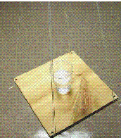
Tumbler of Water on Board Swinging in Vertical Circle (5B)A board about one foot square is swung in a large vertical circle by means of four strings attached to its corners. Before swinging the board adjust your grip on the strings so that they hang with the board horizontal. With practice you can produce this vertical circle even with a tumbler or goblet of water "sitting" on the board. Explain how the water and goblet inertia keep them against the board. |
|
Distortion of Spinning Circle of Spring SteelThe device (5A) used consists of two circular pieces of spring steel mounted on a rod. When the rod is spun (by means of a drill motor or belt driven rotator (12E,H240)) the steel pieces are no longer circular. They must distort for the steel to provide the centripetal force to keep each particle of the band in its circular motion. This can be related to the distortion of spinning astronomical bodies. |

|
Gravity |
|
Coin and Feather Drop (5F)This is the classic experiment that shows that all objects have the same acceleration due to gravity in the absence of air resistance. First, with the tube vertical, flip it 180 several times and observe that the coin falls more rapidly than the small pieces of cloth that play the role of the feather. Then use a hose to connect the tube to the portable vacuum pump. Evacuate until the pump becomes much quieter. Close the valve at the end of the tube, turn off the pump, and remove the hose. Again switch the tube between vertical orientations to show that the coin and cloth now fall with the same acceleration. |

|
Weightlessness of Leaky Bottle (4C)The main device is a plastic pop bottle that has several small holes in the sides not too far from the bottom. There is also a hole in the screw-on cap. Also needed is a bucket or pan to catch most of the water that runs from the bottle. Fill the bottle with water, put on the cap, and hold your finger against the hole in the cap. The water should not run out. With the bottle over the bucket or pan show that the water comes out when you raise your finger from the cap. Stop the flow again. Now drop the bottle into the bucket or pan. The students should be able to see that the water does not come out while the bottle and the water in it are in free fall. A dramatic variation involves the fact that projectiles are in free fall. You can throw the bottle over the heads of some students without getting them wet. Let a student use a bucket to catch the bottle. |
|
Cavendish Balance from Advanced Lab(H230)Shown at left is one cavendish, and at right is a newer type that can be interfaced with a computer. |

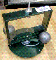
|
Impulse and Momentum |
|
Air Track Collisions (H240,H325)With a portable air track use two carts of equal mass to show all the simple cases: (1) elastic collision with one at rest initially, (2) inelastic collision with one at rest initially, (3) completely elastic collision with two cars moving in opposite direction with same speed initially, (4) completely inelastic collision with two cars moving in opposite direction with same speed initially, etc. In addition to momentum conservation, this demonstration illustrates the fact that, in each case, the forces that the carts exert on one another are equal in magnitude and opposite in direction. |
|
Billiard Ball Newton's Cradle (6A)This nice large cradle was made and donated by Starkville, MS Physics teacher Paul Cuicchi. |

|
Egg DropThis demo is meant to show that, for a given impulse, the force is smaller when the time is longer. Drop an egg onto a foam pad (4A). If you manage to catch the egg on the rebound, it will not be broken. For contrast you can drop the egg into a transparent, hard-bottom, bowl or beaker or you can just use the student's understanding of what would happen. Variations might involve using a rubber egg (6D-dr2). |
|
Catching and Egg in a Sheet(Furnish you own materials.)Hold a bed sheet or table cloth so that it has a "J" profile. Have someone throw an egg at fairly high speed toward the sheet. The sheet will give to stop the egg and then catch it; the egg should be unharmed. CAUTION: Don't miss the sheet. A few years ago the MSU baseball pitcher who still holds the school record for wild pitches did miss the sheet in a physical science class. |

|
Happy and Sad Balls (4C)This demo (involving what are sometimes called happy and unhappy balls) illustrates that twice as much impulse (momentum change) is involved in reversing the velocity of and object as in just stopping it. First show with the two free balls that one rebounds elastically and the other sticks where it hits. Position the two hanging balls so that they are next to the top of the 2X4 block. Pull back the sad (non-elastic) ball so that the string is horizontal. Release the ball and let it swing down to hit the block. The block will be moved some but not knocked over. Repeat the collision with the happy (elastic) ball. The block should be knocked over showing that the impulse was larger. |

|
Track and Low-Friction Carts with Computer Interface (7C)This apparatus accomplishes about the same thing as an air track without the need for a blower. There are two low friction carts which can make elastic or inelastic collisions. It is easy to load more mass on a cart. There are accessories such as propellers, force sensors, and sonic-ranger motion detectors. Some devices can be connected to a computer interface for easy display of parameters. |

|
Two-Ball Drop: Planetary Slingshot Analog (6D-dr1, 6C)Be careful! This demo could cost you some teeth or could wipe out an overhead light. Hold a large ball, such as a basketball, about two feet off the floor. In contact with this ball and just above its center hold a much smaller ball. Drop the two balls simultaneously so that they fall together. Stand back because the small ball will rise fast and to a much greater height than it had when you dropped it. You can approximate this as an elastic collision between the large ball going up and the small ball going down at the same speed. In the limiting case of small ball mass negligible compared to large ball mass the small ball should rise three times as fast as it fell and therefore should reach nine times its original height. It is a similar, although three dimensional, gravitational "collision" with a planet that is used to speed up some space craft on their way much farther out into space. |

|
Center of Mass |
|
Styrofoam Object with LED's(6A)At right are shown two versions of a styrofoam object that has one LED in front of the center of mass and another well away from the center of mass. The irregularly shaped object at left is convenient for throwing and catching. With the lights low, it should be thrown across the front of the lecture room with spin so that the axis of rotation and LED's are toward the audience. The CM LED will be seen to follow a smooth projectile path while the other will have a much more complex path. The L-shaped object at right can be thrown in a similar way. It is also convenient for showing the connection between the CM and stable equilibrium. In the position shown it is stable because CM LED is above the base of support. If the object is rotated 90 counterclockwise and placed down again, it will not be stable. |

|
Box of Various CM Demos(6B)There are several items including a few flat objects whose CM can be determined by hanging each from several different point on the object. There are also several that balance on a single point because the CM is actually below that point. There is a round object tapered in such a way that it appears to roll uphill on a ramp. There is a leaning tower toy that becomes unstable when more mass is added to the top end. |

|
Pendulum Cart(6D)The cart rolls with little friction on its three roller-skate wheels. Hanging from a frame on the cart is a pendulum with a fairly massive bob. With the pendulum oscillating the cart will move in such a way that the CM stays at rest, if it is initially at rest, or moves with constant velocity. This motion also illustrates Newton's laws in that the force put on the pendulum by the cart is "equal-but-opposite" the force put on the cart by the pendulum. The net force on the system is zero and so is the acceleration of CM. Newton's laws can be illustrated in another way. With a rigid obstacle at one end of the cart, pull the pendulum toward that obstacle. While you hold the pendulum in that position, you cause the cart to put a force on the obstacle and the obstacle to put a force on the cart in the opposite direction. The system is in equilibrium, not because the two forces just mentioned are equal in size, but because the force you exert on the pendulum is the same size and in the opposite direction form the force exerted on the cart by the obstacle. When you release the pendulum the obstacle force accelerates the system forward. After losing contact with the obstacle, the center of mass moves at constant velocity. |

|
Third Law |
|
Electric Vehicle on Sheet of Paper(4C)Place the drive wheels of a "tether-controlled" electric toy car on a loose sheet of paper. When the car accelerates forward the force on the paper will be backward and it should move backward. |

|
Propeller-Driven CartThere is a homemade battery-powered propeller cart (4D). There are also propeller attachments for the low friction carts.(7C) |

|
Energy Conservation |
|
Bowling Ball Pendulum(4E)Connect the hook of the chain to the ring in the ceiling in front of the lecture table. While standing upright pull the ball back until it is against your chin. Release the ball and let it swing away and return. Show your faith in energy conservation by not flinching. Have a student test his/her confidence in energy conservation. Ask what would happen if the ball were given a little kinetic energy when it is released. |
|
Chain Reaction of "Dominoes" of Increasing Size (7D)A sequence of properly placed "dominoes" will fall down one after the other when the smallest is pushed over. There is a conversion of gravitational potential energy to kinetic energy as each block falls. Make sure the largest block does not fall off the lecture table and become damaged. |

|
Conversion of Gravitational Energy to Kinetic Energy for Descending Spools(6C)A string or ribbon is wound around the inner part of a spool. With the outer end of this string or ribbon attached to a rigid support the spool is allowed to fall. During its decent gravitational potential energy will be converted to translational and rotational kinetic energy. For any distance fallen the speed of decent of the center of mass will depend on the ratio of the inner spool diameter to the overall moment of inertia of the spool. Consider a race between two spools that are identical except that one has much larger inner spool diameter than the other. |

|
Rotational Motion and Angular Momentum |
|
Moment of Inertia Rods (5D)This demonstration can serve as an introduction to the concept of moment of inertia. It utilizes two PVC pipes that look the same and have the same mass. One has most of the mass (two metal plugs) near the center and the other has most of its mass near the ends. Without explaining the difference between the two rods, have two students each hold a rod near the center with one hand. Ask them to give the rods a large angular acceleration by twisting their wrists back and fourth as rapidly as possible. Of course, the student with the rod with the mass at the center will have an easier time of it. |

|
Large GyroscopeThis large gyroscope has a built in motor that will spin the rotor at fairly low speed. However, many demonstrations work just as well when the rotor is spun by hand and allowed to coast. There is a box of attachments. The weights on the rotor axis screw on and off. For example, one of the weights can be removed or repositioned to allow the torque due to gravity to cause the spinning rotor to precess. |

|
Speed Up of Spinning Student When Moment of Inertia DecreasesHave a student stand on the lazy susan or sit on the stool on the turntable (6E). Hand the student two weights (7E) and ask him/her to hold the weights straight out. Start the student to spinning slowly. Ask the student to pull the weights in against his/her body. As the moment of inertia of the student/weights decreases the angular velocity increase to keep the angular momentum the same. |
|
Angular Momentum of Bicycle Wheel and Spinning StudentHave a student stand on the lazy susan or sit on the stool on the turntable (6E). Hand to the student a spinning bicycle wheel (7E). The total angular momentum about a vertical axis will be conserved. You can illustrate the vector addition of the spinning student and bicycle wheel angular momenta for a variety of cases depending on the orientation of the wheel when you hand it to the student and how the student changes that orientation. For example, you could have the wheel axis vertical when you hand it to the student. If the student then flips the wheel axis to horizontal the student will begin to spin in the same direction that the wheel was spinning initially. If the student flips the wheel axis 180, he/she will spin twice as fast as would be the case if he/she had only flipped the axis 90 to horizontal. |
|
Hoop and Cylinder Race Down InclineUse the long board ramp (hanging under 3) with a very gentle slope. Putting a couple of books under one end is probably steep enough. Start the hoop and solid cylinder (6C) at rest at the top end and discuss why the same one always wins the race. Be sure to catch them at the bottom end to prevent them from being damaged by a fall to the floor. |

|
Direction of Travel of Pulled Spool (6E)In this demonstration a pull on the ribbon around the spool can cause it to rotate clockwise, roll counterclockwise, or slide without rotating depending on the angle between the pull and horizontal. The easiest analysis involves considering torques about the point of contact with the desktop. Torques due to gravity, normal force, and friction will all be zero about this point. The net torque will be the torque due to the pull, giving the three possibilities shown below. |


|
Oscillations and Resonance |
|
Inertia Balance Oscillations(14D)The inertia balance has a platform supported by two pieces of spring steel. Mass sitting on the platform will oscillate back and forth horizontally. It is an easy matter to change the mass on the balance and observe the effect on the period of oscillation. |

|
Resonance of Mass on Spring(6D-dr6&7)Hang from a spiral spring a mass that will give a period of oscillation on the order of a second. Drive the oscillations by means of a very weak periodic force. For example, you can push down periodically with a drinking straw. The straw will bend and provide a very weak force. Show that when the force is in step with the natural oscillations, a large amplitude eventually occurs. For a more elaborate driving mechanism uses weak rubber bands to attach the bottom of the spring (no added mass necessary) to an eccentric pulley (14D-dr6) attached to a belt-driven rotator (12E, H240). Adjust the rotator speed for maximum amplitude of the oscillations of the spring. |

|
Inverted Coupled Pendulum Resonance Device(13A)This device has on each end inverted pendula of three lengths. Each "pendulum" consists of a mass attached to the top of a vertical spring steel rod. The pendula on one end match those on the other. When a pendulum of a particular length on one end is set into motion, with coupling through the base, there will be a resonance oscillation of its twin on the other end but there will be little oscillation of the pendula of different lengths. |

|
Tuning Fork Resonance (13B)Use the two large tuning forks with attached sound boxes (resonant air columns) sitting on a foam pad. One of the forks should have a clamp which can be moved along the fork to change its frequency. Move the clamp toward the fork's tip to lower the frequency. With the two forks sitting on a foam pad, strike one fork and listen for a few seconds before using your hand to stop its oscillations. You should hear nothing from the other fork. Because the frequencies do not match there is no "sympathetic vibration." Adjust the clamp to make the frequencies of the two forks match. (You can use trial and error or you can use beats.) Now strike one fork. Listen for a few seconds and then stop this fork's oscillations. You should now hear a faint sound from the other fork which has been set into oscillation by resonance. |
|
Wilberforce Pendulum Resonance(7B)The Wilberforce pendulum is a combination of a mass on a spring and a torsional pendulum. If the frequencies of these two oscillators match, oscillations of one of them will transfer energy to the other. For example, if you start the mass to bobbing up and down on the spring, soon the mass will be twisting back and fourth. You can adjust the frequency of the torsional oscillator by using the two weights on screw arms to change the moment of inertia. When there is no frequency match there will be little coupling between the two modes of oscillation. |

|
Connection between SHM and Circular MotionOne simple way to show this is just to wedge a tennis ball in the spokes of the bicycle wheel (7E) and let the students view the wheel edge on as it rotates. The ball will appear to bob up and down in SHM. For a slightly more elaborate demonstration use a stiff wire of the shape shown at right (14D-dr6) to attach a ball to a belt-driven rotator. Hang a mass from a spiral spring (6D-dr6&7). Adjust the amplitude of a mass on a spring to match the radius of the circle in which the ball moves. Adjust the period of rotation of the ball to match the period of oscillation of the mass on the spring. With these two moving objects side by side make the point that the vertical component of the balls motion matches the motion of the mass on the spring. You may wish to use a light source (with rays of light parallel to the plane of the circular motion) to cast shadows of the two objects on a screen. As an alternative to the method above you can use a device that converts rotational motion to linear reciprocating motion (13A) or vice versa. |


|
FLUIDS |
|
Ping-Pong Ball Cannon (left of 19)Tilt the cannon with the end opposite the vacuum connection upward. Place a ping-pong ball in the lower end near the connector. Seal both ends with aluminum foil that is smoothed against vacuum grease on the ends and secured by means of thick rubber bands. Alternatively, with no vacuum grease on the ends, seal them with wide plastic packaging tape that laps over and sticks to the sides. Pump out the tube. Puncture the bottom seal and the ball will be propelled at high speed through the top seal. CAUTION: Make sure no one is near the muzzle, and shut off the pump just before the puncture or just after it; the pump will be damaged by pumping for an extended period against atmospheric pressure and also by being left under vacuum while not running. |

|
Water Manometer (19E)Add a little food coloring to the water for visibility. The pressure in the natural gas line us usually low enough to measure with this device. |

|
Three Hole Bernoulli Column (19E)The speed with which the water leaves a hole, and therefore the water's projectile path, can be related to the distance of the hole from the top of the water. |
|
Box of Bernoulli's Principle Demos (19E)Contents include two different types of water-jet aspirator. There are also two different types of bulbs that can be hung close together. Blow between identical bulbs and they will be pushed together by the greater air pressure outside the air stream. There is a ping-pong ball which can be suspended on a stream of air blown from your mouth at a considerable angle below vertical; this takes practice and a steady blow. |

|
Magdeburg Hemispheres (19E)With the two hemispheres joined together (with a little vacuum grease on the mating surfaces) evacuate the space. Close the valve and remove the sphere from the pump. Invite a strong looking guy to pull the hemispheres apart. When he fails, open the valve to admit air and then ask a slight girl to separate the two hemispheres. |

|
Pressure and Bed of Nails (H240)This demo requires only the small bed of nails. Have a student wearing durable jeans sit on the bed of nails. Alternatively press a blown up balloon against the nails. |
|
Air Resistance on Coffee Filters (19E)Establish the dependence of the force of air resistance on speed by noting the higher terminal velocity of two stacked filters over the terminal velocity at which one filter falls. Note the continued increase in terminal velocity as more filters are added. |
|
Smoke Ring CannonsWe have two smoke ring cannons (H240), both of which work the same way. Each has a circular hole in one side and a plastic membrane pulled inward by rubber bands on the opposite side. When the membrane is pulled outward and released, a large vortex ring shoots from the hole. It will remain fairly stable as it travels many meters. They can be used to extinguish a candle or move someone's hair across the room from the cannon. You can make the ring visible by filling the box with smoke or fog (H240) before firing. Unfortunately, this activity is likely to set off the super sensitive smoke detectors in our classrooms resulting in a clearing of the building and a visit from the cops and fire department. Therefore, we must restrict the visible vortex demo to other buildings. |
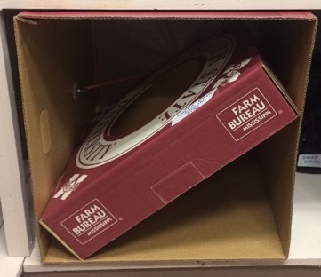
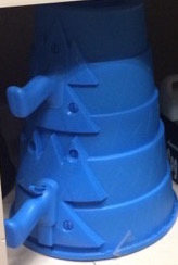
|
HEAT AND THERMODYNAMICS |
|
Crooke's Radiometer 19B)Inside the glass envelope mounted on a needle point are rotating vanes with one side dark and the other highly reflecting. Shine a light on the vanes and they turn with the reflecting sides leading because the residual gas in the envelope is heated more by the highly absorbing dark sides. There is more momentum transfer to gas molecules from this side. If the pressure inside were low enough and the pivot more nearly frictionless, the vanes would turn in the opposite direction because the reflected light would have its momentum changed more than the absorbed light. |

|
Hero's Engine (19B)By means of a tall ring stand suspend the half-filled flask above a bunsen burner. When the water starts to boil jets of steam from the tips of the two tubes will cause the flask to spin. |
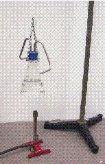
|
Stirling Engine (19B)A small (denatured) alcohol burner heats the cylinder. |

|
PVT Surfaces (19A) |

|
Box of Thermal Expansion Demos (19C)Included in this box is the famous ball and ring demo. When both are at the same temperature the ball is too large to pass through the ring. Heat the ring over a burner and the ball will pass. Never pause with the ball surrounded by the ring or the ring will cool and clamp the ball in such a way that it will be very difficult to remove. There are several bimetallic strips, some with and some without handles. The strips are straight at room temperature but take on considerable curve when heated over a burner. There are two bimetallic strip switches, one connected to two light bulbs in an interesting way. The small metal disks in the box will jump into the air if they are placed on the table while hot. |

|
Thermal Expansion of Long Wire (19C)Attach the test tube clamps holding the two insulators to the tops of two similar ring stands. Plug the power cord into a variac. With the wire cold adjust the ring stands so that so that the wire has very little sag. Use the variac knob to slowly increase the voltage to the wire. The wire should sag. Eventually, the wire should glow and should have considerable sag. For an additional interesting effect bring a magnet near the hot conducting wire. The magnetic force on the wire will be periodic. By trial and error you may be able to get an interesting standing wave pattern. |

|
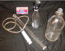
Adiabatic Expansion-Cloud Formation (19C)Have a milliliter or so of water in a clear bottle. With the bottle capped the liquid and vapor will come to equilibrium. Increase the air pressure in the bottle and then suddenly release the pressure. The air should cool nearly adiabatically. With the reduced pressure the air should be supersaturated with water vapor. Condensation will occur. To get enough cloud to see easily you need to seed the air with condensation nuclei in advance. Burn a match near the bottle opening letting a little smoke into the bottle. You won't need enough smoke to see. When the expansion occurs this smoke should provide enough condensation nuclei to provide an easily visible cloud. There are several ways to produce the pressure increase followed by the expansion: (1) Just blow into the bottle with your mouth maintaining the pressure a few seconds before releasing it. (2) Attach a large plastic hypodermic syringe to be bottle by means of tubing and stopper. Push in the plunger and hold the pressure a few second before pulling out the stopper. (3) Use a pump up Fiz Keeper designed to use with pop bottles. A slightly more high tech version of this demo uses a cylindrical plexiglass chamber. Use a large hypodermic syringe to change the pressure. Make the cloud visible by shooting a laser beam through the cylinder in a dark room. |
|
Boiling Water at Room Temperature in Bell Jar(cart)Fill a small beaker about one-third full with water and place it inside the bell jar. Pump out the jar. It will take a while but the water should eventually begin to boil. Repressurize the bell jar and remove the beaker. Let a student feel the water to see that it has gotten cooler rather than hotter. |
|
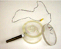
Freezing by Boiling (19B)Place the plexiglass vacuum chamber on the overhead projector. Place water to a depth of 2 to 4 mm in a very light weight, transparent plastic container. (Such a container can be constructed by taping a 1 cm high, 2 cm diameter circular wall of acetate transparency to a >3 cm diameter disk of the same acetate. Support the container on an insulating ring (perhaps cut from a styrofoam cup) inside the vacuum chamber. If you wish to monitor the temperature of the sample, install the lid of the chamber in such a way that the thermocouple is in the sample and connect the thermocouple to an appropriate digital thermometer. Watch the image of the sample on the screen as you pump out the chamber. You have to concentrate on this image for a minute or more or you will miss the main event. The water will quickly boil. Keep watching and eventually the image will become opaque as the sample suddenly freezes. At the instant that the super cooled sample freezes, its temperature will suddenly jump from well below 0 up to precisely 0. Display the temperature by means of the Flex Cam Video Camera(H240) focused on the thermometer display or by means of a thermometer output voltage graph drawn by an interfaced computer. |
|
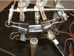
Electrical Conduction by Glass at High Temperature(10A)This demo illustrates that at high temperature even glass will have enough charge carriers to become a conductor. By means of binder clips slipped over glass rods clamp the two ends of a small rectangle of window glass. Use the clip leads of the wiring harness to put the glass in series with a light bulb. Plug the circuit into a wall outlet. The harness has two rocker switches: one a "dead man" switch to make it less likely that you will electrocute yourself and the other a switch that short circuits the light bulb. Use a bunsen burner on an asbestos pad to heat the glass. With the "dead man" switch closed and the other open, when the glass gets hot enough the bulb will begin to glow because the glass is becoming a conductor. Short circuit the bulb and turn off the burner. The current in the glass will continue to heat it and eventually the glass will melt from this resistive heating and separate in a bright flash. |

|
ELECTRICITY AND MAGNETISM |
|
Electrostatics |
|
Classic Pith Ball ExperimentTwo small pith balls hanging from a stand (8C) are observed to repel one another after they are touched by a charged object (8D). The charged object might be a negative hard rubber rod that has been rubbed by fur or it might be a positive glass rod that has been rubbed by silk. You can also show that a ball charged by one of these rods is repelled by the rod that charged it and attracted by the other rod. |

|
Charged Balloons and Glass FlaskIn this variation on the classic pith ball experiment, two inflated balloons (21F-dr1) are hung by strings from a horizontal bar. When both balloons are rubbed with fur (8D), they become negatively charged and repel one another.(left below) A glass flask about the same size as the balloons is rubbed with silk and then is found to attract the balloons (right below). |


|
Uncharged Objects Attracted by Charged Objects(8D)In the classic pith ball experiment we begin with a ball that is attracted to the charged object brought near it. A charged balloon can be stuck to a wall or, perhaps, to the ceiling. Small objects (slivers of paper, grains of salt, bits of aluminum foil, etc.) on a table top can be attracted to a dry drinking straw that has been rubbed with a dry napkin. The most dramatic version of this phenomenon is the attraction of a thin stream of water by a charged object held near it. The water will be diverted considerably from its usual vertical fall. |

|
Various Electroscopes(8B,8C)The photo shows several electroscopes. Just as effective as the commercial models is the one at right that was constructed of some scrap acrylic, some strips of very thin aluminum foil, and a binder clip to hold the swinging strip of foil against the other at the top. |

|
Testing for ConductionCharge (8C) an easily visible electroscope (8C) and then show that you can discharge it by touching it with your finger. Test various materials to see which can form a conducting link between your hand and the charged electroscope. Test various metal, plastic, glass, and wooden rods. Test a small fluorescent tube. For a dramatic finish show that current makes the fluorescent bulb light. Use the electrophorus(8B) as the source of charge. Hold the metal contacts at one end of the bulb in one hand and touch the charged electrophorus to the other end of the bulb. With the lights out the bulb should be seen to flash. Insulate yourself from the floor (with some kinds of shoes you may already be sufficiently insulated) and repeat this flashing exercise several times in succession. Ask the students where all the charge went. Answer: onto you. Touch the far end of the bulb to a water pipe to discharge yourself. You should get an extra bright flash and a bit of a jolt. The students will particularly like to see you flinch. |
|
Conducting Spheres and Other Shapes on Insulating Stands(8C)The small sphere (second from right) can be placed inside the separable sphere (left). |

|
Charging by InductionUse the small metal sphere (8C) on the insulating stand as the object to be charged. Use a hanging pith ball (8C as a detector. Use a hard rubber rod (8D) that has been rubbed with fur as the source of charge. First, for contrast, do charging by contact. Touch the charged rod to the pith ball and then to the sphere. Bring the ball near the sphere and show that it is repelled. "Ground" the sphere by touching your finger to it. Charge the sphere by induction by holding the rod near the sphere while "grounding" the opposite side of the sphere. Remove the "ground" and then take the rod away. Bring the pith ball near to show that it is now attracted. |
|
Electrophorus (8B)This device is a good source for more charge than can be gotten from a rubbed rod. An electrophorus consists of a metal base, a dielectric (wax or plastic), and a conducting plate on an insulating handle. The plate is charged by induction from the dielectric. First, charge the dielectric by rubbing vigorously it with fur. Place the plate on the dielectric. In essence, you are only placing the plate near the dielectric because they contact in only a few places. Ground the top side of the plate. Remove the ground and then lift the plate. The plate will be charged opposite the dielectric. As little, if any, charge is removed from the dielectric, it can be used to charge the plate many times without the need to rub it again. The grounding can be accomplished in many ways. You could touch the top of the plate with your finger. In practice, the easiest thing to do is to slide the plate over so that it touches the metal base. Then slide the plate back away from the base before lifting it from the dielectric. |

|
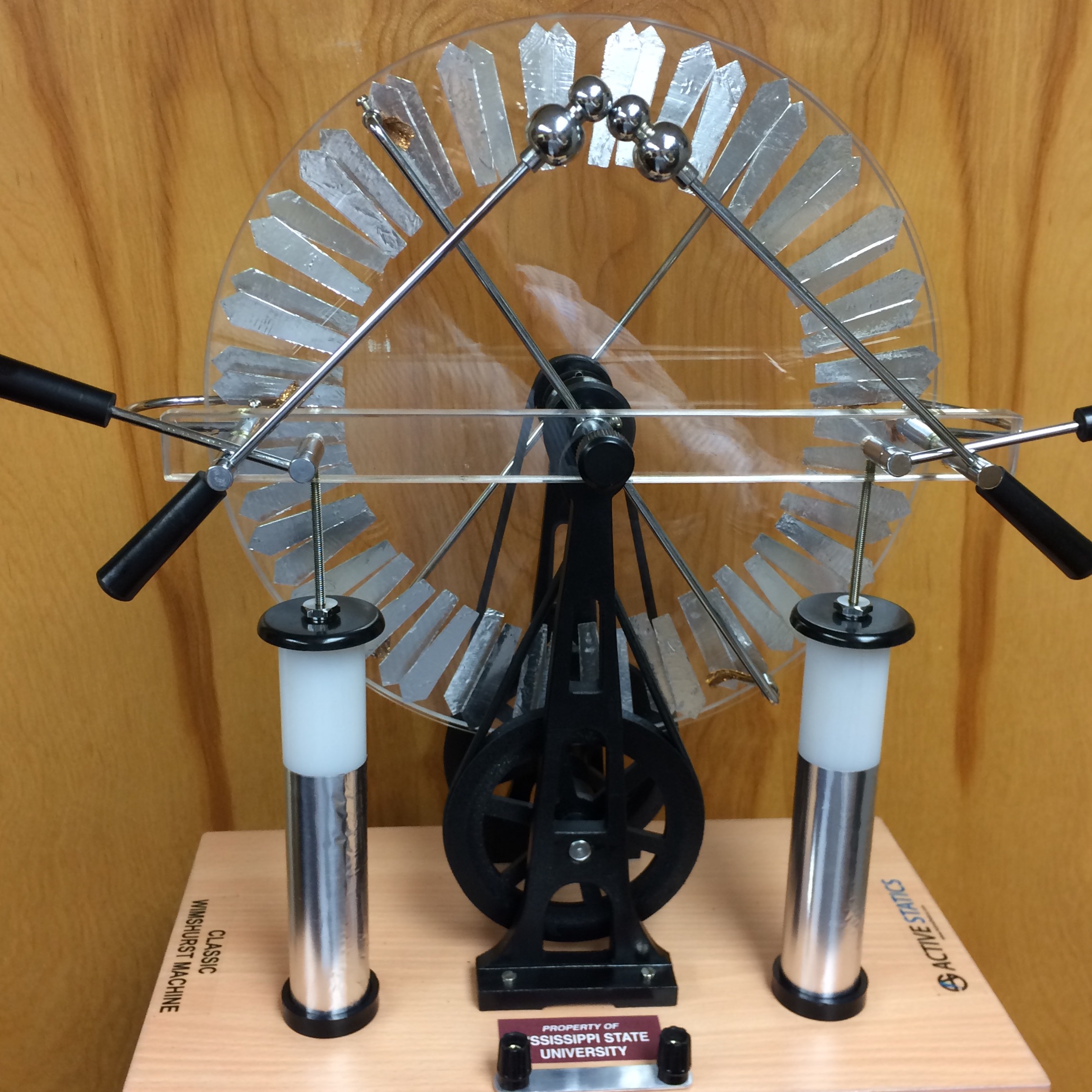
Wimshurst Machine (9E)This device is a good source of charge and fairly high voltage. Use it to illustrate the breakdown of air. The size of the spark gap between two small metal spheres is controlled by means of two large insulating handles. The smaller handles nearby are used to connect the electrodes to two leyden jars. With these connected the capacitance is greatly increased as evidenced by the much greater cranking time it takes to get the voltage high enough for a spark. These sparks should be hot enough to poke a hole in a card held between the balls. To literally add a little spark to your presentation you can hold one of the balls and let the spark jump from your finger to the other ball. Unless you want this to hurt make sure the leyden jars are not connected. |
|
Van der Graff Generator (9E)This well known device can produce voltages higher than those from the whimshurst. Get an idea of the maximum voltage by the length of the sparks you can draw to the small grounded sphere. The generator works best when very clean. If it is performing poorly, use alcohol to clean the dome inside and out. If you do the standard hair standing on end demo, seek out a girl with fine clean hair. Have her stand on a plastic box (9A). Be patient; it may take a while for the hair to stand up much. With this small machine you are unlikely to come obtain the dramatic effect often seen in textbook photographs. On days when this demo does not work very well salvage things by putting a cup of foam peanuts on top of the generator. They should float away as the dome charges. One former professor jazzed up his demonstration by holding the dome with one hand while he brought a finger of his other hand near a bunsen burner which had gas flowing to it. A spark jumped from his finger and lit the burner. |
|
Charge Confined to Surface of Conductor (8C)Charge a pith ball and the small sphere on the stand and show that they repel. Place the small sphere concentrically inside the sphere that comes apart into two halves. Only after the outer sphere is closed move the small sphere over to contact the larger one on the inside. Pull the small sphere back to the center and separate the halves of the bigger sphere. Show that the pieces of the big sphere are charged and that the small sphere is not. |
|
Electrostatic Bells (9F)Touch a charged electrophorus plate to the top of the center post of the bell assembly. This charges the outer bells. The bells will ring as the clappers are attracted to the outer bells, share some of the charge and then are repelled, move to the inner bell, share charge with it and then get repelled back to the outer bells. The process repeats for some time. |

|
Dissectable Leyden Jar (9C)The photo shows the disassembled leyden jar along with some accessories. Connect the outer can and center electrode of the assembled leyden jar capacitor to the terminals of the whimshurst by means of ball chains. With the whimshurst's two leyden jars disconnected turn its crank to charge the leyden jar. Use the ball tipped curved conductor on the insulating handle to discharge the leyden jar to show the spark. It may take some trial and error to know how much charge to put to get a good spark. Charge the capacitor again. Use the hook on the insulating handle to remove the chains without discharging the capacitor. Then use the hook to lift the inner conductor out of the insulator. Use the tips of your fingers to remove the insulator from the outer conductor. Touch the two conductors together. You should observe almost no spark. You may then pass the two conductors to one or mor students for inspection. Reassemble the leyden jar. In the last step be sure to use the insulated hook to reinstall the inner conductor. Then discharge the capacitor and note the large spark that comes from what seemed to be a discharged capacitor. This reveals the importance of polarization of the dielectric. There is controversy about the complete explanation. |

|
RC Circuit (9C)On a breadboard we have a series circuit consisting of a 9 V battery, a large capacitor, and a flashlight bulb. The current through the bulb will decay exponentially whether the capacitor is charging or discharging. The time constant is such that the changes in bulb brightness are easy to see. Use a small wire on the breadboard to change between charging and discharging. |
|
Circuits |
|
Batteries and Bulbs (8E)Rather than a demonstration, this exercise is often done by the students at their desks. To establish the idea of a complete circuit and to build familiarity with batteries and bulbs the first task is to light one bulb by using it with only one wire and one D cell battery. Then progress to up to 4 batteries and several bulbs in various combinations of series and parallel. |
|
Large Cenco Lecture Table Galvanometer (10F)This large meter can be used as a galvanometer, a voltmeter, or an ammeter. Resistors stored on the back are required for all but galvanometer operation. In galvanometer mode the meter is quite sensitive and will be damaged if connected directly to any battery or power supply. The meter is most useful for showing currents induced in coils of wire by changing magnetic fields. The open construction of the meter makes it useful for showing how such a meter works. |

|
Various Projection Galvanometers (10E)Two of these meters can be used with the overhead projector and the other (at far right) uses an optical lever to project a spot of light on a scale. All are very sensitive and should be used very cautiously to avoid damaging them. The small Pasco meter (left front) can be used as a voltmeter and has several voltage ranges. |

|
Electric Pickle (10C)Stick a fork in each end of a large dill pickle and connect clip leads of the wiring harness to the two forks. Make sure the forks are not close to touching one another. With the pickle over a dish to catch any dripping juice, plug in the harness and depress the rocker "dead man" switch. This connects the pickle to 120v ac. The pickle will conduct and eventually glow brightly. Spectroscopic investigations indicate that much of the glow is from excited sodium atoms. It may be necessary to sand the forks a bit in advance if they are badly tarnished. Please clean up the forks and plate before putting them back in the box. |

|
Parallel and Series Bulbs (10C)The wiring of these two sets of three sockets is easy to see. Besides showing both arrangements with identical bulbs it is interesting to show the parallel case with three different bulbs, e.g. 40 W, 75 W, and 120 W, and then ask the students which bulb will be brightest if these three bulbs are put in the series set of sockets. |

|
Swinging LED Demonstration of AC Current (8B)This demo has a bicolor LED (in series with an appropriate resistor) at the end of an ordinary electrical cord. When the LED is swung in a circle in a darkened room it draws a dashed circle of alternating red and green light. Begin the demonstration by showing that such an LED (also in series with an appropriate resistor) lights red for one direction and green for the other direction of current supplied by 9 V battery. The dashed circle then provides evidence that the current from an ordinary outlet is alternating in direction. A similar demonstration that uses a neon bulb at the end of a cord draws a dashed circle of only one color. |
|
Chassis Ground: Lighting a Bulb with Cart as Return Lead (8E)Use one of the unpainted metal carts. First show the lighting of a #47 bulb connected by means of two leads to a 6 V lantern battery. Then remove the negative battery lead from the bulb and connect that lead to the cart. Touch the bare terminal of the bulb to the cart at another location to show the wiring pattern used in automobiles. |

|
Household Ground: Lighting a Bulb with Water Pipe (10B)CAUTION: This one can kill you if you aren't careful. Use an extension cord that has a grounded metal outlet box. The cord that is provided for this demo has a "dead man" switch that must be held depressed for the outlets to be live; this should make it harder for you to electrocute yourself. Plug the bulb into the hot (short) and neutral (long) slots of the outlet by means of test probes. To make good contact the probes need to be near the centers of the slots. The bulb should light. Remove the probe from the hot slot and plug it into the ground (round) opening. The bulb should not light. Replace this probe in the hot slot and move the probe from the neutral slot to the ground opening. The bulb should light. If the extension cord is plugged into a ground fault interrupter (GFI), as it will be if it is plugged into the lecture table, the GFI should click off before the bulb lights. The GFI will have to be reset; under the lecture table, press the button on the face plate of the outlet. To avoid this situation plug the cord into an outlet that does not have a GFI. (There should be such outlets in the walls of the room.) Repeat the operation with the probe moved from the neutral to the ground slot. The bulb should light. Now move this probe so that it is touching the metal box. The bulb should light. Finally, move this probe so that it is touching the water pipe. Again, the bulb should light. |
|
Pasco Interface Display of Voltages in RLC Circuit
You will need to use the Pasco Science Workshop 750 Interface (21C) and a computer that has the "Data Studio" software installed.
Connect the computer to the video projector.
Connect the interface to the PC by means of the USB cable and to power by means of its adaptor.
Use the Blue Pasco Circuit board (21C).
The output terminals on the right front of the interface will supply the ac signal.
Using two banana leads connect a series RLC circuit with
To activate your display do the following:
(1) Double click the "Data Studio" icon.
(2) At the main menu select "Create Experiment."
(3) In the "Sensors" window double click on "Voltage Sensor" three times.
This will place A, B, and C sensors on the picture of your interface.
(4) In the "Signal Output" window (below sensors window) double click on "Output." This activates your sine wave signal source.
That is, it makes the output of the interface the input to your circuit.
Set the amplitude for 1 volt and the frequency at 2500 Hz.
Drag the output control box to the lower right of your screen.
(5) In the "Displays" Window, in the bottom left corner of the screen, double click on "Scope." This makes your PC act as an oscilloscope.
Accept "Voltage A." Enlarge the oscilloscope screen as much as possible without covering your frequency and amplitude control box.
(6) From the top left "Data" window drag channels B and C onto your oscilloscope screen.
Also drag the output onto the screen.
You now have a four channel oscilloscope.
(7) By clicking the appropriate arrows below and to the right of your oscilloscope display change the sweep to
You should now have four traces displayed. You may find it easier to observe their relative phases if you click the "Stop" button to freeze the trace. Click "Start" again before changing parameters. It will be interesting to see the effect of increasing frequency. By using the frequency + button of the output control window scan the frequency up to about 5500 Hz, the approximate resonance frequency for this circuit. Note the large and approximately equal capacitor and inductor voltages. Insert the iron core (stored in a clip at the left of the circuit board) into the inductor. The effect of the increased inductance should be dramatic. Scan the frequency down to find the new resonant frequency. |

|
Magnetism |
|
Variety of Magnets (11F)Shown at right are some of the magnets available, ranging from the large magnetron magnet at left to the small ceramic magnets at front. There are also several high field neodymium magnets used with specific demonstrations. |

|
Magnetic Deflection of Electrons-Discharge TubeShown at right is a very low pressure tube (11A) in which a beam of electrons is accelerated to high speed. The electrons pass through a slot and then leave a streak on a phosphor. A magnet (11F) can be used to deflect the beam. The high voltage is supplied by an induction coil (11C) that is powered by a 6 V battery. It may take trial and error to get the appropriate polarity so that the electrons leave their streak on the phosphor. |

|
Magnetic Deflection of Electrons-OscilloscopeMore convenient than the discharge tube demo above is the use of an old oscilloscope (9F) to supply the electron beam. With no voltage on the oscilloscope's deflection plates only a spot will be seen on the phosphor at front. A magnet (11F) can be used to move this spot around. |
|
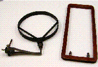
Magnetic Force on a Current (11E)Use a clip lead several meters long. Hold the wire so that a loop of it dangles between the poles of a large strong magnet such as a magnetron magnet. Very briefly connect the ends of the wire to the terminals of a 6v storage battery. The wire should deflect. Reverse the polarity and the deflection should be in the opposite direction. Don't leave the circuit connected for more than a second. Rather than a clip lead, you may find it convenient to use one of the rectangular wire frames in the box for this demo. In any case do not leave the battery connected very long. |
|
Audio Speaker (14D)Make intermittent very brief contacts of the leads of a speaker to a small battery and note the movement of the paper cone in response to the magnetic force on the coil glued to that cone. Also note the sound made. |
|
Magnetic Field of a Current (11C, 12D, 8E-dr1)Use a compass on the overhead projector to detect the field of a clip lead connected briefly to a 6 V storage battery. |
|
Collection of Coil Shapes for Overhead Projector(12D)Use these current carrying conductors with a low voltage battery or power supply. Use a compass or iron filings to reveal the field directions. |

|
Magnetic Force Between Two CurrentsThis device (in front of the shelves just under 10A,11A, 12A) uses long wires clamped to the two ends of a piece of metal conduit. When the conduit is near horizontal the two wires dangle well below the it. If a current is sent through the wires they will exert a magnetic force on one another. Rather than a dc source, use a step-down transformer (10B) to supply ac current to the wires. The two wires are electrically connected to the conduit at the end far from the transformer. The transformer can be connected to the wires in two ways. The current can go out one wire and back the other giving currents in opposite directions or the current can go out both wires and return in the conduit giving currents in the same direction. With the conduit pointed toward the students or above their heads, there will be a noticeable deflection of the wires while there is current. Do not leave the transformer connected for more than a second or two. |

|
Thermocouple-powered Electromagnets (11B)The left magnet in the photo has a large thermocouple that can be heated with a bunsen burner. With the magnet securely mounted on a rod, the iron end plate will support several kilograms. At right in the photo is a water heater gas valve with a thermocouple-powered magnet to keep the valve open when the pilot light heats the thermocouple. |

|
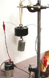
Strong Electromagnet (11C)This magnet has a coil surrounded by an iron housing. When this part is combined with the load bearing iron end plate there is a closed magnetic circuit which enables the magnet to support a load much larger than the 1kg shown in the photo. A 6 V lantern battery provides adequate current. Don't leave the battery connected any longer than necessary for the demonstration. |
|
Box of Solenoids (10D)Among the coils in this box is an automobile solenoid that is an electromagnet that both electrically connects the battery to the starter motor and mechanically applies the starter gear to the flywheel gear. |
|
Suspended Button Magnet Stack Compass (12B)Suspend a stack of four Neodymium button magnets by a monofilament thread about half a meter long with its lower end trapped between magnets. As the person holding the thread rotates slowly 360 the magnet stack will be seen to keep its same orientation in space. To make this orientation more apparent you can trap between the center two magnets a card with the two sides labeled differently. (The card will also damp the, otherwise long lasting, torsional oscillation.) One end of the stack will be seen always to point north. This end can be labeled the N-pole. It is, of course, pointing toward the Earth's geographical north and toward the Earth magnet's S-pole. |

|
Various Electric Motors (12C)Shown at right are some of the demonstration dc electric motors. Most have delicate parts that easily get out of position. You may have to do some minor repairs before using these. Power them briefly with a 6 V battery. They may overheat if operated for more than a few seconds. |
|
Faraday's Law |
|
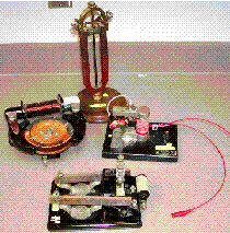
Box of Earth Inductors (10D)These coils were originally designed to use with ballistic galvanometers to show voltages induced by the Earth's magnetic field when the coils changed orientation. The Circular coil was meant to be used with a mechanical rotator. It has a commutator that can be contacted by means of two spring steel brushes. The rectangular coil is useful as a prop in discussions of torque on a current in a magnetic field. This coil can be connected to a large galvanometer and moved near a strong magnet to show induced voltages. |
|
Jacob's Ladder: Step-Up Transformer(H240)The high voltage transformer is connected to two nearly vertical wires inside a plexiglass shield. Rising air currents cause the arc between the wires to rise. A new arc always strikes at the bottom where the wires are closest together. For your protection: the power cord has a "dead man" switch that must be held closed for there to be current to the primary of the transformer. Even with this switch you must exercise caution to avoid getting near bare electrodes. The heavy apparatus is equipped with casters to allow you to roll it slowly to class. Pull the apparatus by means of the string attached at bottom front rather than pushing it by means of the delicate upper part. |

|
Small Tesla Coil and Bulbs(10B)Screw in the knob on the end to activate the tesla coil. Hold a bulb in your hand and then let the tesla coil spark to the metal of the bulb. There should be an interesting glow. Because of the high frequency and resultant very small skin depth you will hardly feel anything. |

|
Large Tesla Coil (H240)This coil is about a meter high. |

|
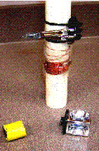
Flashbulb Faraday's Law DemoA coil wound around one end of a piece of PVC pipe (standing to left of 19) is connected in series with a flashbulb from an old Kodak Flashcube (11C). The picture shows the bottom end of the pipe. With the pipe vertical, a neodymium magnet is dropped into the pipe. The current that is induced in the coil by the passing magnet sets off the flashbulb. |
|
LED's on Pipe Lighted by Falling MagnetThis is similar to the flash bulb demo above except in this case there are a number of coils along a PVC pipe (standing to left of 19). Each has attached to it an LED. As a Neodymium magnet (11C) falls through the pipe it lights the LED's one after the other. |
|
Eddy Currents in Pipe Due to falling MagnetIn this demonstration a Neodymium magnet (11C) falls through a copper or aluminum pipe (standing to left of 19). Eddy currents induced in the pipe exert a retarding force on the falling magnet. It takes several seconds to fall through the pipe. For contrast, drop an aluminum plug through the pipe. |
|
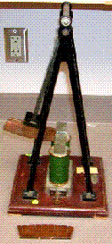
Eddy Currents in Swinging Copper Plate (11E)The copper plate is the "bob" of a pendulum and swings between the poles of an electromagnet. Adjust the pendulum and magnet to make sure that the plate swings between the magnet poles without hitting. Show how the plate swings with no power to the magnet. Then, with the magnet connected to a 6 V battery, let the pendulum swing again. The damping should be obvious. Do not leave the battery connected any longer than necessary. Replace the solid plate with a slotted plate to show the decreased damping. |
|
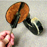
Eddy Currents in Spinning Disk (11F)Use a pizza-cutter-like copper disk. Give the disk a spin and show how long it will coast. Then spin it again and hold it between the poles of a strong magnet. The eddy current damping should be evident. |
|
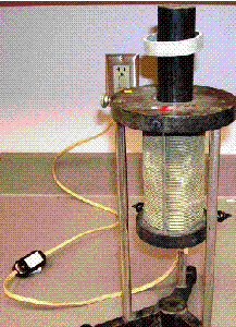
Jumping Ring-Heated Ring (11E)Use the large vertically mounted 120v ac solenoid with the movable iron core. Extend the core upward until its bottom is about even with the bottom of the coil. Place the aluminum ring on the core. When the power is switched on to the coil the ring will jump well above the top of the core. Be prepared to catch it. Superficially, the explanation is that the induced current in the ring is opposite the current in the coil giving a repulsive force. More careful analysis of a whole cycle will lead to the conclusion that the force should be attractive for half the time with an average force of zero. Even more careful analysis would have to take into account the resistance of the ring and the effect that it has on the phase difference between the coil current and the ring current. If you hold the ring and do not let it jump off the core, it will quickly become quite hot. You can let a student do the holding or you can toss the hot ring to a student who can tell the rest of the class about how hot the ring gets. What we have, of course, is a step-down transformer with huge current in the ring secondary. When you are finished store the ring on the bottom of the lowered core. |
|
Turn-by-Turn Transformer Demo (11E)This demonstration uses the same vertical solenoid as does the jumping ring demo. Also needed are a 6v flashlight bulb in a socket and a clip lead several meters long. Mount the bulb on a stand so that it is easily seen by the students. Attach the ends of the clip lead to the two electrical connectors of the bulb socket. With the solenoid connected to 120v ac and with its iron core extended upward at least six inches, wind the clip lead wire one turn at a time around the core. As more turns are added the bulb will begin to glow and will increase in brightness with each added turn. |
|
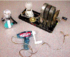
Hand-crank Generators (12C)The old generator, at upper right in the photo, has a coil that is rotated by the crank. The crank is quite easy to turn when there is no load but will become noticeably harder to turn when the switch button is pressed to light the bulb. In the "Y2K" hand-powered flashlight, at left in the photo, a magnet rotates inside a fixed coil. To show the effect of the load, note how long the magnet will coast with the bulb in the circuit. Then slightly unscrew the bulb/lens assembly to remove the bulb from the circuit and again note how long the spinning magnet coasts. The Genecon at the bottom of the picture works as either a motor or generator. Connect two of them together and have one act as a motor and the other as the generator that supplies the current. |
|
Cenco Motor/Generator(12C)Depending on the arrangement of the brushes and connections to a 6 V battery the device at right can be used as a dc motor, dc generator, or ac generator. |
|
Tri-color LED Lenz Law Demo (11C)This demo utilizes the two-in-one kind of LED that lights red for current in one direction and green for the other direction of current. Begin by connecting such and LED (in series with an appropriate resistor) to a 9 V battery. Use both directions of current to familiarize the students with the LED. Connect another such LED (without resistor) to the two ends of a coil that has thousands of turns. Push the coils between the poles of a large magnetron magnet. Then pull the coil away. The LED will have a different color when leaving the magnet than it did when approaching. Repeat with the coil or magnet turned over. |
|
Super Sensitive LED Lenz Law Demo (11C)This demo is similar to the tri-color LED version but uses a high gain op-amp amplifier to make it much more sensitive to small flux changes. There are in this case separate red and green LED's to indicate the direction of induced current. A sensing wire or coil can be connected to the amplifier/indicator by means of banana plugs. With a coil with thousands of turns the LED's will light even if the coil moves very slowly near a magnet. The amplifier/indicator is sensitive enough to display flux changes due to the Earth's field. You can use one of the so-called earth inductors that were originally used with ballistic galvanometers. Connect one to the amplifier. Flip the coil over in the Earth's field and you can see the red and green LED's alternately light. You can use a long wire as a sensing "coil". Swing the wire jump-rope fashion in the Earth's field. |
|
WAVES AND SOUND |
|
Waves |
|
Transverse and Longitudinal Waves on Long Spring (13C)Use one of the springs that can be stretched to several meters in length. Secure one end to a wall or stand. At the other end make a transverse pulse by plucking upward and releasing a small part of the spring next to the hand that stretches it. Have the students note the reflected pulse that comes back. Repeat this several times until they clearly see that the pulse is tuned upside-down on reflection. To make a longitudinal pulse stretch or compress a small region of the spring and release it. The longitudinal oscillation of the spring will be more evident if you have white tape markers as several points. |
|
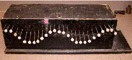
Antique Hand Crank Transverse Wave Simulator (13F)This device works because of eccentrically mounted disks that support the rods which are tipped by white balls. As the crank is turned the harmonic wave shape moves across the machine. Point out the simple harmonic motion of each ball. This machine is very good for showing that a particular wave feature, e.g. a crest, moves one wavelength in one period of oscillation. |
|
Torsion Wave Device (hanging under 2)This device has equally spaced dumbbells mounted on a spring steel band about three meters long. You send a wave along it by giving the end dumbbell a twist around the band. The pulse will propagate slowly and will reflect. The kind of reflection will depend on whether the far end of the band is rigidly mounted or is held by a long string and is free to rotate. |

|
Sound |
|
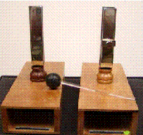
Tuning Forks with Sound Boxes(13B)These two tuning forks are nearly matched; one has an movable clamp for adjusting its frequency. One fork can be used as a vibrating sound source. It can also be used in showing the resonant coupling to the attached column of air in the sound box. The box is somewhat less than one-fourth wavelength long. Cover the opening to show that the air column does, indeed, amplify the sound from the fork. The two forks can be used together to demonstrate resonance or beats. |
|
Nail Violin-Nail Guitar (14B)This small guitar-shaped board has a row of nails with exposed lengths that make them vibrate at frequencies close to those of musical notes. The nail sequence for Mary Had a Little Lamb is written on the board. The nails can be struck with a pencil or bowed with a violin bow. |

|
Double Sonometer (H240)This is a very large two-string instrument with built-in spring balances to indicate the tensions in the "strings." |

|
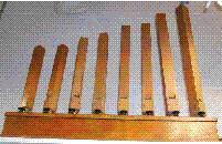
Eight Pipe Octave Organ (H240) |
|
Matched Vibrating Bars(13B)These two bars have attached sound boxes. They can be used in a way similar to the two matched tuning forks. To produce beats you can change the frequency of one bar by sticking a small piece of modeling clay on it. |

|
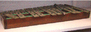
Barphone (H240) |
|
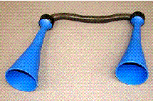
Transmission of Sound Through Long Spring (14A)Sound made at one horn is transmitted to the other end though the spring. |
|
Martin's Spinning Speed of Sound Measurement Device (14F)This apparatus consists of a spinning disk, with a white index mark, and two photographic flash units with attached sound trigger devices. The flash units are positioned to illuminate the spinning disk. One sound sensor is placed close to the disk and the other farther away. In a darkened room, someone near the sensor that is farther from the disk claps his hands. As this sound reaches the two sensors at different times the two flashes illuminate the disk at different times. The angular distance between the two white index positions seen can be related to the speed of sound. If necessary, use a strobe light in determining the rotation speed of the disk. |

|
Sound Spectrum with Audio Oscillator and PA SystemConnect an audio oscillator to the lecture room PA system by means of banana plug wires inserted into the blue box mounted under the center of the lecture table. Scan through frequencies throughout the range of hearing. |
|
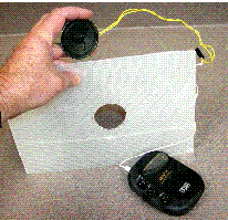
Speaker Baffle Interference(14D)Attach a two inch speaker to a small radio by means of the ear phone jack. Tune the radio to a local station. Let the students hear the poor quality and volume of the sound. Place in front of the speaker a piece or cardboard or other material with a hole just large enough to leave the speaker cone uncovered. The sound will greatly improve. One explanation is that without this baffle the waves from the front and back of the speaker cone interfere destructively. They are out of phase in the sense that when the speaker cone is raising the pressure in front of the speaker it is lowering the pressure behind. Both of these pressure waves propagate to the audience. With the back wave impeded by the baffle, you get the full effect of the front wave. |
|
Two Speaker Interference (14E)The sound sources are two inch speakers that have styrofoam cup baffles in front. The speakers are supported on a horizontal rod. Make the rod free to swing about a vertical axis by clamping onto a ring stand a close fitting ring that will prevent the clamp holding the horizontal rod from sliding down. The clamp then need not be tightened onto the ring stand. Connect the speakers to an audio oscillator that is putting out a sound wave of 1-3 kHz. Ask the students to cover one ear. Rotate the rod supporting the speakers so that the distance difference for each student will change. Ask if they hear the changes in loudness. Because of the non linear response of the ear many of the students may be uncertain. Because of complications, including reflections from the walls, you will not get complete destructive interference for anyone. A change by a factor of two or more in intensity may be hardly perceived by listeners. For a clearer indication of the changes in intensity use a small crystal microphone some distance from the speakers to pick up the sound. Connect this speaker to a high-gain amplifier and the amplifier output to an oscilloscope. The sound signal will then be seen on the screen. As the speakers are moved, changes in intensity of the displayed signal should be evident. |

|
Standing Waves-Resonance |
|
120 Hz Standing Waves on a String (13F)This involves the same apparatus used by the students in experiments in several of our labs. A 120 Hz vibrator moves one end of a string. The other end passes over a pulley to a weight hanger. The mass on the hanger can be adjusted to produce various harmonics. The frequency is always 120 Hz but you are adjusting the sound speed, and therefore the wavelength, to make different numbers of half wavelengths fit on the string. |
|
Computer Controlled Standing Waves on a String (14D, 21C)This makes use of a Pasco Mechanical Vibrator, a Pasco Science Workshop 750 Interface, and a PC that has "Data Studio". Connect the interface to the PC by means of the USB cable and to power by means of the power adaptor. Connect the output terminals of the interface to the input terminals of the vibrator by means of banana leads. Using no more than a few newtons of tension and making sure that the vibrator drive post is locked in position, stretch an elastic band from the vibrator post to some other support. Release the drive post. Run "Data Studio." Select "Create Experiment." Double-click on "Output" in the small "Signal Output" window. This should give you an output control box that lets you control a sine wave signal fed to the vibrator. Set the amplitude for no more than two volts. Use the arrows to decrease the frequency interval from 100 to 0.1 or 1 Hz. If the "Auto" button is selected, turn it off so that you can use the "On" and "Off" buttons. Use the + button to scan the frequency upward until the string vibrates in its fundamental mode. Scan higher for other modes. |
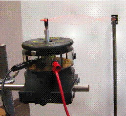
|
Standing Waves on a Long Spring(13C)Attach one end of a long string to a support and stretch the spring across the front of the room. By moving your hand that holds the end of the spring up and down periodically with small amplitude you should be able to produce large amplitude transverse standing waves of the fundamental and several other harmonic frequencies. |
|
Singing RodThe source of sound in this case will be an aluminum rod or brass pipe (standing to left of 19) that is vibrating longitudinally in a standing wave pattern. These vibrations are excited by friction. Spray the sides of the rod near one end with baseball pitchers rosin or rub it with violin bow rosin (14D-dr1). Grip the rod tightly at its (marked) center with thumb and forefinger of one hand. With the other hand on the tacky portion of the rod, pull toward you. It will take some trial and error to find out how much pressure to put with this pull. When you get it right you will cause the rod to squeal at high frequency. You can add to the intensity with each additional pull until the sound is very loud. The mechanism for setting up the vibrations is a grab-and-slip resonance similar to that of a violin bow on a string. |
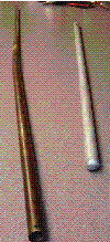
|
Air Column ResonanceConnect an audio oscillator (13E) to the small speaker (14E). Hold the speaker near the top of an air column such as that in a drinking glass or piece of pipe. Vary the frequency until the sound is amplified by the air column. Continue to scan the frequency until you find higher harmonics. CAUTION: Not every loudness is air column resonance. The speaker itself may have a resonant frequency at which its sound output is greater. |
|
Twirl-A-Tune (14E)This is a flexible corrugated tube which gives off sound when one end is held and the other is swung rapidly in a circle. A sequence of more than one harmonic will be heard as the tube slows down. |
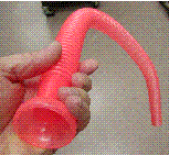
|
Heat-Driven Singing Pipes (14E)With these devices sound is generated by the turbulence in hot air rising through a mesh. The length of the pipe determines the frequency that will be amplified and heard. In one kind of pipe (shown at right) there is a wire mesh closer to the end that should be used as the bottom end. Hold the pipe above an ordinary bunsen burner and lower it so that the mesh will be heated. Raise the pipe above the flame and the air that rises through the mesh will vibrate at many frequencies. The pipe's fundamental will be amplified and easily heard. You can ham up your presentation, and make the students think, in the following way: Have the pipe in one hand and a tumbler or other container in the other. After the pipe starts to sing tilt it over to horizontal as if you are pouring something from it into the container. While you are doing this the sound stops. Tilt the pipe back to vertical as you pretend to pour something back into it from the container. Ask the students to explain or start them thinking by giving a ridiculous explanation such as that the heat puts sound into the pipe and that the sound can be stored temporarily in the container. The mesh in the pipe is unnecessary if you use the Mecker type of burner that has many holes or a grill at the top. In this case you will get the sound while the pipe is down around the top of the burner. With a little trial and error you will be able to find the correct position to get a loud low note from a fairly long piece of PVC drain pipe. CAUTION: In either version of this demonstration the pipe can get hot! |
|
LIGHT |
|
Reflection and Refraction |
|
Various Water Tanks (15B)To make a laser beam show up in the water tank add a tiny pinch of powered coffee creamer to the water. To make the beam outside the tank show up use chalk dust. |
|
Blackboard Optics (16D)This is a set of reflection, refraction, and focusing demonstrations in a box. The light paths from a single-ray projector (lower right in the picture) or multi-ray projector (lower left in the picture) are seen as the light scatters from the surface of the chalk board. The projectors are attached to the board by means of strong magnets and they are powered by 12 volts from a power supply or battery eliminator (8F,12F). (There is a long white extension cord that makes it unnecessary to have the power supply near the ray projector.) There are clear plastic pieces in the shape of a block, a prism, a semicircle, and several lenses. There are magnet-secured brackets for holding these pieces against the board. For some demonstrations it is easiest to just hold these refracting pieces with your hand. |
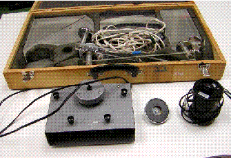
|
Bending Light Beam (15B, 15C)Into the water tank that is about 10 cm long and 50 cm long put enough water to fill it about a third to half way. Add a tiny amount of coffee creamer to scatter light. Position a laser at the end of the tank so that the beam can be seen passing through the tank a centimeter or so from the bottom. It may be necessary to put the tank up on blocks. Now pour into the tank some sugar solution. The solution can be made by mixing about a cup of sugar with about two cups of hot water. Add a little coffee creamer to this also. The solution should be cool before it is used in the demonstration. About a cup of the solution should be sufficient for one demonstration. As you move along the tank from the laser end to the center pour the solution in gently trying not to stir the water up too much. It may work best if you pour the solution in through a long stem funnel with the tip at the bottom of the tank. After the turbulence settles down, the beam will be seen to curve downward dramatically. In the case shown at right the beam reflects off the bottom of the tank and is bent downward again. It is easy to use Fermat's principle to explain the bending. You can relate this bending to similar bending of sunrise and sunset light in the Earth's atmosphere. It is the reverse of the kind of bending that gives mirages. |

|
Total Internal Reflection (TIR) |
|
TIR in Blackboard Optics Semicircular Block (16D)With the single ray projector attached to the chalk board hold the semicircular plastic block so that the beam is normal to the curved surface. Keeping this condition move the block so that the angle of incidence on the flat face increases past the critical angle. |
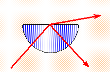
|
TIR in Blackboard Optics Prism (16D)With the single ray projector attached to the chalk board position the plastic prism to demonstrate both of the cases shown at left. |
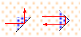
|
Rigid Plastic Light Pipes (15D) |
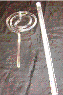
|
Water Stream Light Pipe (15D)In this demonstration light is trapped by TIR in a stream of water exiting a plastic bottle through a hole in its side. Stopper the hole and fill the bottle. Add a tiny amount of coffee creamer to scatter light. With the laser on a tripod, position the beam to hit the stopper. With the room lights off, remove the stopper. The stream will be red because of the light that scatters from the trapped beam. To ham up your presentation catch some of the water in a container into which you have secretly put a little red food coloring. When the lights are back on pour out some of the red water and make some ridiculous comment about the light trapped in it. |
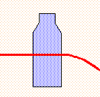
|
Frustrated TIR (15C, 15D, 18D-dr6)Use two 45-45-90 prisms with their long faces together. Send laser light nearly perpendicularly into one of the short faces so that the light will be totally reflected at the long face. Squeeze the prisms together until some of the light leaks through the very thin layer of air between the prisms. At right is shown an assembly that is useful for this demonstration. A short ring stand has a clamp that holds two suitable prisms. |
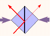
|
Magic Drawing Board or Glo-Doodler (17C)This child's toy, manufactured under several names, exhibits several physics principles. It consists of a flexible fluorescent sheet of plastic over a white background. When a writing stylus is pressed against the sheet, bright fluorescent writing is seen. The sheet absorbs room light of short wavelengths and emits light at longer wavelength. Most of the emission directions are such that the light is trapped in the sheet by TIR. Note the bright edge of the sheet. When the sheet is pressed close to the white backing, light escapes into the backing by frustrated TIR. There some of the light is scattered back through the fluorescent sheet. |
|
Image Formation |
|
Plane Mirror Flying Trick (15F)Stand on a table with a large plastic mirror between your legs in such a way that the reflecting side is toward the students. One of your legs will be hidden but the students will see the front leg and its reflection making it seem that they see both legs. Lift the foot that is in front of the mirror off the table. It may be useful to have a block of wood behind the mirror under your back foot. It will appear to the students that both of your feet are off the table. You are flying. Ham it up by flapping your arms or by reaching back and grabbing the back of your belt to appear to be lifting yourself. |
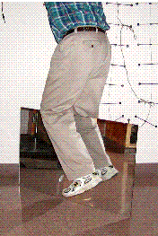
|
Illusion Box (17C)In this small toy a small model airplane seems to be suspended in space. Actually there is just half a plane attached to a diagonal mirror. |
|
Real Image of Light Bulb (H240)was 16A, 17A, 18AA large concave mirror forms a real image of a light bulb. (See a photo of the image at left.) The bulb is hidden from view inside a box. (See the photo at right.) There is a bulb socket on the outside of the box above the bulb. If the bulb is positioned one mirror radius from the mirror the bulb's image will be at the socket. Students looking into the mirror will seem to see a bulb in the socket. It takes a little trial and error and a little shimming up of the mirror to get the image just right. Briefly place a sheet of paper at the image to show how a real image can be formed on a screen. Consider positioning the arrangement so that the students will see it when they arrive for class. You can move the bulb closer to the mirror to get a larger image perhaps on the projection screen. A projection cart is not big enough to hold this demo. There is an appropriate piece of plywood (stored in the 16A-17A corner) that can be placed on top of a cart. As an alternative to the image by a mirror, form an image by means of a large lens. A suitable lens is mounted in a board on a stand that can be used with the light bulb in the box. Note: There are two of these apparatus—one grey, one maroon—stored adjacent to one another at (H240). |
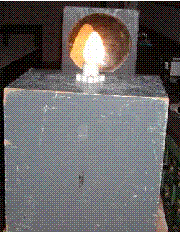
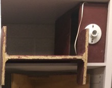
|
Slide Projector Lens ReplacementRemove the usual lens from a slide projector (16A) and hold various other converging lenses (18D-dr5&8) between the projector and the screen to show how they can form real images. Include in this demonstration a half lens or half-covered lens to emphasize that it is the curvature of the refracting surfaces and not the shape of the rim of the lens that determines the imaging properties. Shown at right is an old slide/film strip projector with its usual lens folded aside. Two possible imaging lenses are shown. |
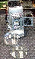
|
Blackboard Optics Ray Tracing Through Lenses (16D)Use the multi-ray projector attached to the chalk board along with one of the plastic lenses. Adjust the output mirrors of the projector for five parallel rays. Note the focal point where the rays meet. Both spherical and chromatic aberration may be evident. |
|
High Resolution Vision Only at Center of RetinaWhile you stand at one side of the front of the classroom have the students stare at something on the other side. Hold up several fingers and ask the students to tell you how many without moving their gaze. Move toward the side that they are staring at until they are able to tell you the number. This illustrates that we have densely packed visual cells that give perception of image details only near the center of the retina. |
|
Spectrum and Color |
|
Color Vision Only at Center of RetinaWhile you stand at one side of the front of the classroom have the students stare at something on the other side. Hold up a colored object and ask the students to tell you what the color is without moving their gaze. Move toward the side that they are staring at until they are able to tell you the color. This illustrates that we have densely packed cone cells for perceiving color only near the center of the retina. |
|
Spectrum Formed by Prism (15D)We have a Blackboard Optics single-ray projector mounted on a stand with a prism (see at right). Connect the single-ray projector to a 12v supply (8F,12F). Place this stand on a table or cart no more than a couple of meters from the projection screen and adjust the positions so that light goes from the single-ray projector through the prism and on to a spectrum on the screen. Room lights should be off. |
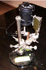
|
Spectrum of Overhead Projector Light Formed by Grating (17B)This method forms a much more useful spectrum than does the prism. Attach a piece of holographic diffraction grating to the output lens of an overhead projector by means of a single piece of tape. Position the grating so that the "lines" are vertical. Use two pieces of cardboard to form a slit on the overhead projector stage. The slits image on the screen should be vertical. With the room lights out and the projector on, the slit's image will be the zero order spectrum. On each side of it you should see a very bright first order continuous spectrum. (An interesting variation is to replace the slit with an anti slit; remove the two pieces of cardboard and put a thin strip of cardboard where the slit was. Try to interpret the "spectrum" that you now see on the screen.) |
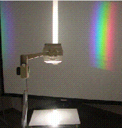
|
Hand Out Gratings (18D-dr7)Pass out to the students the holographic diffraction gratings in 2x2 slide mounts. Position several light sources at the front of the room for them to view through their gratings. Use and incandescent bulb and several gas discharge tubes to show the difference between discrete and continuous spectra. There is a three-source stand that can be used for viewing three spectra simultaneously. |
|
Colored Shadows (16B)The apparatus has red, green, and blue aquarium lights. With these lights on, use them to cast shadows of your hand on the projection screen. Explain the color combinations seen. For example, where only the green light is casting a shadow you will see magenta, the sum of red and blue. |
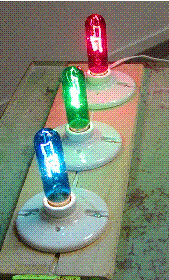
|
Color Mixing Box (16A)This device has red, green, and blue light sources controlled by switches and brightness controls. The sum light appears on a frosted screen at the front of the box |
|
Tinker Toy Color Mixing Device (16B)With the overhead projector pointing away from the screen, place the base of this device (with the three holes and color filters) on the projector stage. Unfold the device and position it so that each of the three small mirrors intercepts one color of light coming through the filters. Use the Tinker Toy mounts to adjust the mirrors until you have three colored disks of light on the screen. Adjust the mirrors to make different colors overlap so that you can show how the primary colors add. |
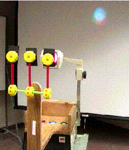
|
Colored Filters on Overhead Projector (17B)Use red, green, blue, cyan, magenta, and yellow plastic filters on the overhead projector. Ask the students to predict which color will be seen where two filters overlap. Remind them that a filter looks the color(s) that it does not absorb. For example, where red and green overlap black will be seen because red absorbs green and blue and green absorbs red and blue. However, where red and magenta overlap red will be seen and where yellow and cyan overlap green will be seen. |
|
Spectrum of Light Transmitted by Color Filters (17B)Make use of the spectrum formed by a grating attached to the overhead projector. Note what is missing from the spectrum when a colored filter is placed over the slit formed by the two pieces of cardboard. |
|
Colored Object in SpectrumMake use of the spectrum formed by a grating attached to the overhead projector. Place colored objects in the spectrum. For example an orange painted object in the blue part of the spectrum should look dark. However a fluorescent orange object in the blue part of the spectrum will look orange. Alternatively, rather than form a complete spectrum, use a sodium lamp as your light source and examine the appearance of various colored objects. |
|
Projected Spectrum of Mercury (17B)CAUTION: Do not view the mercury lamp directly. The spectroscope consists of a mailing tube with a hole in the side for the mercury lamp. At one end the tube is covered by a sheet of holographic diffraction grating and a thin fresnel lens. The distance from the lamp hole to the lens is a little more than the lens focal length. Use this lens to form a spectrum on the screen as shown at right. To reveal some of mercury's ultraviolet lines place a fluorescent card just inside the violet line. If you have someone in the class who has had cataract surgery, it is likely that this person will see the uv lines without aid of a fluorescent card. |
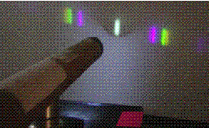
|
Electromagnetic Spectrum-Ultraviolet (18C)Use and ultraviolet light to illuminate various fluorescent objects such as starch and fluorescent cards. |
|
Electromagnetic Spectrum-Infrared and MicrowavesWith the room lights off show how the TV remote control (17C) causes the orange patch on the IR detector card to flash. Aim the control's LED at the card from a few cm away and press one of the buttons. The card must be "charged" first by exposing it to room light for a few minutes. The microwave detector is of the type used to detect leaks from microwave ovens. You can also use the klystron microwave source and the diode detector(17F) with matched horns. |
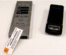
|
Interference and Diffraction |
|
Near Point Source-Concentrated Arc Lamp (18B)This source is about as close to a point source as you can come although a Mini Mag Lite with the lens housing removed does pretty well. Use the point source to see diffraction patterns through slits between fingers or slits in sheets of paper. The concentrated arc lamp lights only after momentary application of the start switch. Below at right is the design for a diffracting sheet to pass out to the students or have them construct for themselves. At the center of the dashed rectangle is a cut made by a razor blade or box knife. As a student looks through the slit toward the point source, he/she can tug gently at the edges of the paper to increase the slit width. Inside the dashed circle is a tiny pinhole made by the tip of a straight pin or needle. If the edges of the hole are smooth enough it will produce a nice Airy disk with rings. |
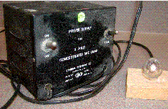
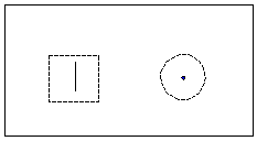
|
Double Slit Interference (H330A)Use an optical bench, laser, and slits from the elementary laboratories. Also use a couple of lenses to make a low power telescope to increase the size of the interference pattern on the screen. For example, a +127mm focal length lens followed by a -22mm focal length lens will form a galilean telescope that can be focused to give enlarged fringes on the screen. To show the effect of blocking one of the slits use a razor blade held by a large binder clip. |
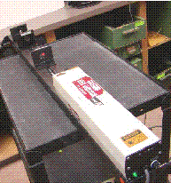

|
Effect of Slit Width on Width of Diffraction Pattern (H330A)Use an arrangement similar to that above with single slits of various widths. Alternatively, have the students view some concentrated source of light through a slit cut in a piece of paper. Let them note what happens when the sides of the slit are pulled farther apart. |
|
Soap Film Interference Projection (16C)Use the device that has a projection bulb mounted on a frame above a black board. Turn this device on its side with the bulb closer to the screen than the board and with the board approximately parallel to the screen. Near the board place a small open bottle of bubble solution and above the bottle opening suspend (ring down) a small bubble blowing ring of the type that comes in small bottles of bubble solution. Position the converging lens (mounted on a black wooden block) so that it will image the ring on the screen. Raise the bottle to put a film of solution on the ring. Reposition the ring so that the reflection from the film hits the image on the screen. It may take a few tries to get this right. As the film drains (up as seen in the real image) and gets thinner, colored interference fringes will be seen. As the film gets still thinner at the top (bottom on the screen) the fringes will disappear and the film will appear dark. This destructive interference for nearly zero path difference gives evidence the phase difference caused by one internal and one external reflection. You may need to use a cardboard screen to keep the bright light from blinding the audience. CAUTION: The lamp gets very hot. Don't get anything very near it and don't touch anything that has been near it. |
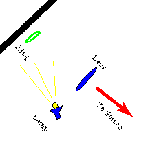
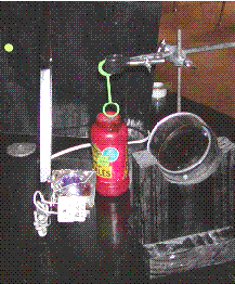
|
Gasoline Film on Water Projection (16C)This is a difficult demonstration to get right but some folks like it. Use the projection bulb on the frame that is mentioned in the previous demonstration. Place the black board on the overhead projector and position the lamp a short way from the projector's lens. ("Short way" has to be at least 10 cm or you will melt the projector.) Do not turn on the projector. Position a small black saucer of water under the lens so that the lamp light reflects from the water into the projector lens so that the water surface is imaged on the screen by that lens. Put a small drop of gasolene on the water. If you have things set up right, after the film becomes thin enough you will see a colored interference pattern on the screen. |
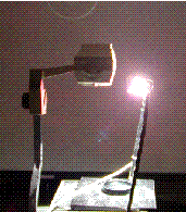
|
Thin Air Film Between Pieces of Plate Glass (16E)At right is shown one version that has two large pieces of plate glass clamped together to make the air film between them quite thin. Note the dark places where the negligible film thickness gives destructive interference because of the reflection phase difference. You can use smaller free glass plates or microscope slides under filtered green light from a mercury lamp to get visible interference even when the film is thick enough to exceed the coherence length of white light. The Flex Cam Video Camera(H240) can be used to display this interference to the whole class at once. |
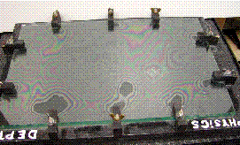
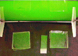
|
Polarization |
|
Linear Polarizer for Microwaves (17F)Plug in the source and aim its horn into the horn of the detector. Let the source warm up for at least a minute before adjusting any controls. If the detector indicates no signal adjust the source control slightly. Once you have a signal slowly adjust the source and detector controls until the detector needle indicates near full scale. Point out that the source produces vertically polarized waves and that the detector consists of only a vertical diode and a microammeter. Tilt the source or detector to show the reduced detected signal when the electric field of the waves is not parallel to the diode. Show the slotted aluminum plate and indicate that it acts as a polarizer for microwaves. Ask what orientation of the plate will best transmit the vertically polarized radiation. The students usually say that the slots should be vertical to transmit and horizontal to block the waves. Show them that the opposite is the case. Point out the role in absorption played by the currents caused in the aluminum. |
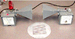
|
Polarization by Scattering (15B)Put a tiny amount of powered coffee creamer into a tank of water. Send through the water a beam of unpolarized light, for example from a slide projector with a slide with a small hole in it. With a large sheet of polaroid show that the scattered light is polarized perpendicular to both the incident and scattered directions. Alternatively, place a polaroid between the source and tank to show that more light is scattered when the transmission axis of the polaroid is perpendicular to the scattered direction. If you use an internal mirror He-Ne laser as a source, the intensity of scattered light will change as the polarization of the incident light changes. If you use a red laser pointer, your source is polarized. |
|
Polarization by ReflectionThe idea is to use a piece of polaroid to analyze the polarization of light scattered from a piece of glass. One method is to pass out microscope slides and small polaroids to students. Alternatively use a piece of glass to scatter overhead projector light onto the projection screen and show the effect of a polaroid between the glass and screen for various angles of incidence. Point out that polaroid sunglasses are used to reduce glare from horizontal surfaces. |
|
Random Polarization of Internal Mirror He-Ne Laser(15C)Place a polaroid between a He-Ne laser and the screen. The spot on the screen should change in brightness with time. The changes will be more rapid when the laser is first switched on. Typically, such a laser emits most of its light in a superposition of two longitudinal modes that are polarized perpendicular to one another. As the laser cavity changes length the amplitudes of the two modes change. The total intensity in the two modes changes little with time; hence you don't notice much intensity fluctuation without the polaroid. By trial and error you may be able to find the polarizer postion which gives little change in transmitted intensity with time. This position of the polaroid transmission axis bisects the two mode polarization directions. The changing polarization of these He-Ne lasers makes them poor sources for many polarization demonstrations. |
|
Polarization of Laser Pointer (15C)As you can verify with a polarizer the output of red laser pointers and other red diode lasers is nearly linearly polarized. The output of green laser pointers, however, appears to be unpolarized. |
|
Calcite Crystal(18D-dr9)Place the crystal over a mark on a transparency on the overhead projector. Two images of the mark will be seen. Rotate the crystal about a vertical axis to show that one of the images rotates about the other. Use a polaroid to investigate the polarization of the light giving each image. |
|
Stress Birefringence of Squeezed Lucite (18D-dr6&9)Use two wooden bars connected at one end by a bolt to squeeze on a round lucite plug that is between crossed polarizers on the overhead projector. There are other shapes of clear plastic that can also be stressed between crossed polarizers. |
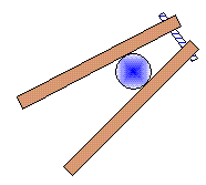
|
Stress Birefringence of Cellophane and Clear Plastic(18D-dr9)Many clear plastic materials including many cellophane package covers and most clear plastic boxes are stressed during their manufacture. Crumple or fold a piece of cellophane and place it between crossed polarizers on the overhead projector. You should see brilliant colors. At any location the color seen will be the compliment of the color that is removed because for that color the cellophane acts as a full wave plate and maintains the plane polarization of the light allowing it to be blocked by the second polarizer. Similar colors will be seen for clear plastic boxes such as those used to store CD's or cassette tapes. |
|
MODERN PHYSICS |
|
Fluorescence(18C)Use a black light to illuminate various fluorescent objects. Note that the color seen is not present in the illuminating "light." You can also use blue or violet light to illuminate a fluorescent orange or yellow card showing that the wavelengths seen are longer than those of the illumination. One possible source of this blue light is from the spectrum of white light formed by a grating attached to an overhead projector. Among the interesting fluorescent materials are starch, teeth, fluorescent chalk, and laser dye. You can also point out the fluorescence going on in the Glo Doodler. |
|
Cloud Chamber (18F)Tracks of high speed charged particles become visible when the charges along the path provide condensation nuclei for a super saturated vapor. You will need to prepare the chamber (in the location where it will be viewed) about 20 minutes beforehand. |
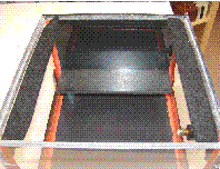
|
|
Remove the glass top from the chamber and apply anti fog solution to its top surface. With the chamber removed from its base, prepare the cloud chamber by pouring several ounces of denatured alcohol on each of the two felt wicks at the sides of the top of the chamber. Then pour enough alcohol on the floor of the chamber to barely cover it. (CAUTION: The alcohol is flamable and its vapor may be explosive! Avoid flames or sparks.) Place the base of the chamber on a level surface and, if necessary, use the leveling screws to make sure the chamber will be level. Fill the aluminum tray in the base with liquid nitrogen to within about one-half inch of its top. |
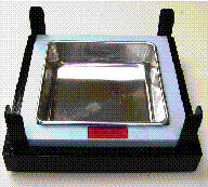
|
|
Place the chamber onto the base and the glass top onto the chamber. Being careful not to block either the brass-fitting source holder in the side of the chamber or the thick Plexiglas window at the lower back, surround the bottom of the chamber with the black cloth skirt to help keep air currents from the liquid nitrogen area. Place the slide projector about 18 inches from the back of the chamber so that the light will enter through the thick block of Plexiglas. It will take about 20 minutes for the alcohol vapor to get established so that the super saturated region near the bottom of the chamber will reveal particle tracks. The chamber should continue to work for about a half hour before new liquid nitrogen is needed. When you are ready to view tracks turn on the slide projector and dim the room lights. Once it is dry, rubbing the outside of the top cover with silk will establish an electrostatic field that will help sweep charged droplets to the bottom of the chamber and provide a clear region for new tracks. |
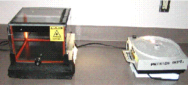
|
|
With no source in the chamber and the plastic plug rod in the source holder, tracks due to cosmic rays, radon in the air, and other natural sources should be evident. For frequent alpha particle tracks, remove the plug from the source holder and insert the thorium-alloy rod. The rod will be held in the proper position when the plastic rod in which it is imbedded is snug in the source holder. An alternative source of alpha particles is 241Am from a smoke detector. Such a source is available on a small stainless steel button mounted in the tip of a modified gray Euro Ball pen. Remove the tip cover and insert the source into the chamber through the source holder. A dense spray of alpha particles will enter the chamber. (Actually, the source has been covered with clear tape in which there is a small hole. Without this alpha-limiting tape too great a flux of alphas would enter the chamber and after about a second the tracks would no longer be visible because the appropriate vapor environment would not be maintained.) For electron tracks remove the plug and other sources and place the 14C disk source in the recess in the outer part of the source holder and secure this source with the set screw. Either have the students come by one at a time to view the tracks in the chamber or use the Flex Cam Video Camera(H240) to project the image of the bottom of the chamber onto the screen. When you are finished with the chamber wipe off alcohol and condensed water. Leave the glass cover off so that the alcohol can evaporate from the wicks. When the chamber is dry and clean, return it and the accessories to shelf (18F). |